Planning an efficient fodder cutting area layout is one of the most overlooked steps in setting up a livestock operation, yet it directly determines daily throughput, labour cost, and machine lifespan. A well-designed workspace moves raw material from storage to the cutter, through the cutting chamber, and into collection with minimal lifting, minimal downtime, and enough clearance for the operator to work safely and clean the machine at the end of every shift. This guide walks through a practical workflow — storage, feeding, cutting, and collection — and explains which machine dimensions and discharge details you must confirm with the manufacturer before pouring a slab or fixing a discharge chute.
Chaff cutter in operation — note the infeed direction, discharge throw, and operator standing position.
Why Layout Planning Matters More Than Machine Capacity
Many buyers select a chaff cutter based on rated capacity alone and then discover that the real bottleneck is material handling. A machine rated at 800–1500 kg/h cannot reach that figure if the operator spends most of the shift walking to a distant haystack or shovelling cut fodder off the floor. Capacity on the specification sheet is a machine figure; effective capacity is a workflow figure.
A practical layout addresses four zones in sequence:
- Raw material storage — where bales, loose straw, green fodder, or silage are held before cutting.
- Feeding zone — the operator's standing position and the infeed table or conveyor.
- Machine zone — the cutter itself, with clearance for maintenance and blade access.
- Collection zone — where cut fodder lands, is bagged, or is conveyed to a mixing or feeding point.
Each zone needs floor space, headroom, and a defined flow direction. The goal is a straight or gently curved line from storage to collection, with no backtracking.
Zone 1: Raw Material Storage and Pre-Staging
Storage design depends on the material you process most often. Dry straw and hay bales need a dry, ventilated area away from the cutting zone to reduce dust at the machine. Green fodder and silage are heavier and wetter, so the storage floor should drain freely and tolerate wheelbarrow or cart traffic.
As a planning rule, hold at least one full working day of raw material within a few metres of the infeed. For a mid-sized operation running a machine in the 600–800 kg/h class for four to five hours, that means roughly 2.5–4 tonnes of staged material. Larger operations running a higher-capacity unit should scale the staging area accordingly.
Practical storage guidelines:
- Keep bales stacked no higher than a comfortable single-lift height for the operator.
- Leave a clear aisle of at least 1.0–1.2 m between the stack and the feeding zone for cart access.
- For wet silage, position storage slightly below or level with the infeed so material can be pushed or forked forward rather than lifted.
- Separate dry and wet staging areas where possible — mixing dust with moisture creates a sticky residue that builds up in the cutting chamber.
Zone 2: The Feeding Position and Operator Access
The feeding zone is where safety and productivity meet. The operator must be able to stand comfortably at the infeed with stable footing, push material in at a steady rate, and step back quickly if needed.
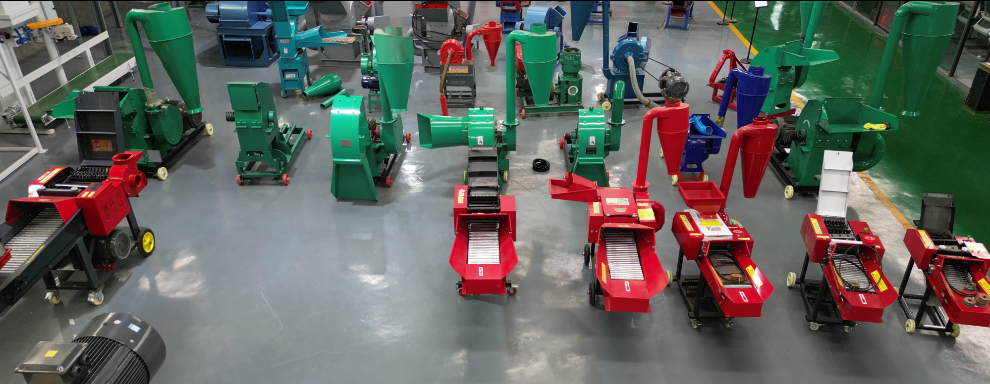
Typical chaff cutter configuration — infeed table, cutting chamber, and discharge chute orientation.
Key feeding-zone requirements:
- Operator standing space: at least 0.8 m of clear depth behind the infeed table, allowing the operator to lean in and push material without overbalancing.
- Infeed height: confirm the infeed table height from the manufacturer. A table too low forces bending; too high makes it hard to control long straw.
- Side clearance: leave 0.5–0.8 m on at least one side of the machine so the operator can reach the power switch, clear a jam, or access the blade cover.
- Anti-slip flooring: wet green fodder makes floors slippery. Grooved concrete or rubber matting in the feeding zone reduces slip risk.
- Emergency stop reach: the stop control must be reachable without the operator letting go of the material.
For a vertical-model machine such as the Vertical chaff cutter machine (model 2.8) — 4KW motor, 600–800 kg/h capacity, suitable for wet and dry material — the vertical infeed means material is fed downward into the cutting chamber. The operator's position and the staging height should match this top-feed orientation. For a horizontal model such as the Horizontal chaff cutter machine (model 2.8), also 4KW and 600–800 kg/h, material is fed along a horizontal plane, which changes the ideal staging and operator stance.
Zone 3: Machine Zone — Dimensions and Clearances to Confirm
Before finalising the layout, obtain the following from the manufacturer. These are the figures that determine the machine footprint and the space around it.
| Detail to Confirm | Why It Matters | Typical Planning Allowance |
|---|---|---|
| Overall length × width × height | Sets the machine footprint and headroom | Add 0.5 m each side for access |
| Infeed table height and length | Determines operator posture and staging height | Match to operator ergonomics |
| Discharge chute height and throw direction | Determines collection zone position | Allow for full material arc |
| Motor power and electrical connection point | Fixes cable route and switch position | 4KW or 5.5KW typical |
| Weight and base fixing points | Determines floor loading and anchoring | Confirm with slab design |
| Blade access side | Sets maintenance clearance | 0.5–0.8 m clear |
| Wet/dry material suitability | Affects drainage and cleaning provision | Confirm per model |
For higher-throughput operations, the Vertical chaff cutter (model 3.8) offers a 5.5KW motor and 800–1500 kg/h capacity, also handling wet and dry material. The larger motor and higher throughput generally mean a heavier machine and a more substantial discharge throw, so the collection zone and floor fixing should be planned for the larger unit rather than the smaller one.
Exact dimensions, weights, and base-fixing details vary by model and should be confirmed directly with the manufacturer before the floor slab is cast or the discharge chute is fixed in place.
Zone 4: Collection — Managing the Discharge Throw
Collection is the zone most often mis-planned. Cut fodder leaves the discharge chute with real velocity, and the material arc can extend well beyond the machine footprint. If the collection point is too close, material piles against the machine; too far, and the operator wastes time raking.
Collection options to plan for:
- Open floor collection: simplest and lowest cost. Allow a clear arc in the discharge direction and rake or fork material into a barrow or cart.
- Bag or sack collection: position the bag frame directly in the discharge arc. Confirm the chute height so bags can be swapped without lifting above shoulder height.
- Conveyor or blower to a mixing or feeding point: used in larger operations. Requires a fixed discharge direction and a level or slightly rising conveyor path.
- Direct discharge into a feed mixer or TMR wagon: the cleanest workflow but requires the mixer to be positioned within the discharge throw.
Whichever option you choose, confirm the discharge chute height and throw direction from the manufacturer. Some models allow the chute to be rotated; others are fixed. This single detail determines whether the collection zone sits to the side, behind, or in front of the machine.
Cleaning, Drainage, and End-of-Shift Workflow
A layout that ignores cleaning will degrade quickly. Wet green fodder and silage leave residue in the cutting chamber, on the infeed table, and on the floor. Plan for:
- A floor drain within a few metres of the machine for wash-down water.
- A sloped floor (typically 1–2%) toward the drain in wet-material areas.
- Clear access to the blade cover and chamber for daily cleaning and blade inspection.
- A water point nearby for rinsing the chamber and infeed table.
- Cable routing overhead or in conduit so hoses and water do not contact electrical connections.
End-of-shift cleaning should take no more than 10–15 minutes on a well-laid-out floor. If it takes longer, the layout — not the operator — is usually the problem.
Matching Layout to Capacity and Material
The right layout depends on how much material you process and what form it arrives in. As a planning summary:
- Small farms, mixed wet and dry material: a compact footprint around a 4KW / 600–800 kg/h machine, open floor collection, manual cart staging.
- Medium operations, higher daily tonnage: a 5.5KW / 800–1500 kg/h machine with a defined discharge arc, bag or conveyor collection, and a dedicated staging aisle.
- Commercial feed processing: fixed discharge into a conveyor or mixer, concrete drainage floor, and separate dry and wet staging bays.
In every case, confirm machine dimensions, infeed height, discharge throw, weight, and base-fixing points with the manufacturer before finalising the floor plan. These figures are model-specific and should not be estimated.
Conclusion
A productive fodder cutting area is designed around the workflow, not just the machine. Staging material close to the infeed, giving the operator stable footing and side clearance, allowing a full discharge arc for collection, and planning for daily cleaning will let your chaff cutter run closer to its rated capacity and last longer. Before you commit to a floor slab or fix a discharge chute, confirm the exact dimensions, infeed height, discharge throw, weight, and base-fixing details for the model you are considering. The team at FCN.FM can provide model-specific dimension drawings, capacity guidance, and OEM/ODM configuration advice to help you finalise a layout that fits your material, your daily tonnage, and your site — get in touch to discuss your requirements.
References
- https://www.chaffcuttermachine.com/
- https://www.chaffcuttermachine.com/chaff-cutter-machine/
- https://www.osha.gov/laws-regs/regulations/standardnumber/1910/1910.212 (general machine guarding principles applicable to feeding zones)
- https://www.hse.gov.uk/agriculture/topics/machinery.htm (agricultural machinery safety and operator access guidance)